Stack
Libraries, tools, and project deliverables
These sections reflect the authored stack in this repository tree. The reusable libraries and
fwtool include quick-start tutorials with small examples. The local senior-project components
are described here as project deliverables instead of reusable packages.
Together they show why the project grew beyond a single firmware tree. Some pieces exist to keep embedded
development repeatable, while others exist to get the real system built, flashed, tested, and demoed.
Read this section from top to bottom and it moves from formats and parsers, to generated hardware and
firmware infrastructure, to the project-specific pieces needed to demo the full system.
Fig itself is a small configuration language with its own normative spec. That distinction matters in this
project because the language rules are not just whatever the current Zig parser happens to accept.
The spec is aimed at hardware, embedded, and networking work. It borrows the broad shape of TOML, but it
keeps the grammar smaller and adds the parts that actually matter here: tagged headers, semantic versions,
bit ranges, and deterministic declarative merge rules.
Design Goals
The spec keeps the language small on purpose. It is supposed to be readable in source form, easy to
implement without a giant parser stack, and precise enough to describe generated hardware manifests
without drifting into ad hoc string conventions.
- Readability, determinism, and declarative merge behavior are explicit goals in the spec.
- Native literals cover integers in multiple bases, floats, booleans, strings, versions, bit ranges, and enum literals.
- The intentional differences from TOML are part of the design: comments are
//, arrays are {...}, and tags belong in headers.
Repo Structure
The spec repo is more than one long syntax document. It also carries the design rationale, mapping
boundary notes, and conformance direction for future implementations.
SPEC.md is the normative language document.docs/design-rationale.md explains why tags, merged declarations, and homogeneous arrays exist.docs/mapping.md defines the boundary between Fig structure and consumer-side typing.
Semantics That Matter
What makes Fig useful for generated hardware and embedded config is not only the scalar syntax. It is
the document model. Tables can be reopened, dotted keys and headers merge to one structure, tagged
entries publish structural names, and positional sequences can mix explicit indices with append-style
entries.
[server] and server.port = 8080 merge into the same nested table.[[register: CR1]] lets later headers refer to CR1 as a structural name instead of a positional slot.[@root] resets header context back to the document root.- Plain value arrays are homogeneous values, not path-addressable scopes.
- Current spec version:
0.5.0.
- Written for hardware, embedded, and networking configuration rather than generic app-config sprawl.
[peripheral: SPI1]
base_address = 0x40013000
version = 1.2.0

[SPI1.clock]
source = "HSI"

[[SPI1.register: CR1]]
offset = 0x00
Core notation
The fastest way to get a feel for the spec is to read a few small patterns instead of starting with
the whole language document. These are the constructs that show up constantly in real config and
manifest files.
- Use dotted keys or table headers interchangeably when they describe the same structure.
- Use
{...} for homogeneous value arrays and [[...]] for repeated tables.
- Use header tags when the domain name matters more than the container name.
- Use
version and bitrange literals directly instead of inventing string encodings.
Tables and dotted keys merge
server.host = "localhost"

[server]
port = 8080
Value arrays versus table sequences
ports = {80, 443, 8080}

[[endpoint]]
path = "/health"
method = "GET"
Tags, versions, and bit ranges
firmware = 1.2.3

[[register: CR1]]
bits = 0:7
access = .RW
fig-zig is the Zig implementation of the Fig spec. It is the parser, raw-table builder,
mapper, and validator that turn .fig source into typed Zig values.
The important architectural point is that this repo is not only a file loader. It takes the language
through several clean phases: munch-based lexing and parsing, structural merge into a raw
table tree, then typed mapping into ordinary Zig structs and slices.
Parser Pipeline
The checked-in implementation is explicit about each stage. lexer.zig exports a
FigLexer built on Munch, parser.zig produces the typed AST,
raw_table.zig merges the document into one structural tree, and
type_map.zig maps that tree onto the caller's Zig type.
parseBytes(...) and parseFile(...) both go through the same parser, raw-table, and mapper path.- Syntax diagnostics come from the parser; structural merge errors come from the raw-table pass.
- The raw-table layer is what makes reopened headers, tagged entries, and dotted integer paths merge deterministically.
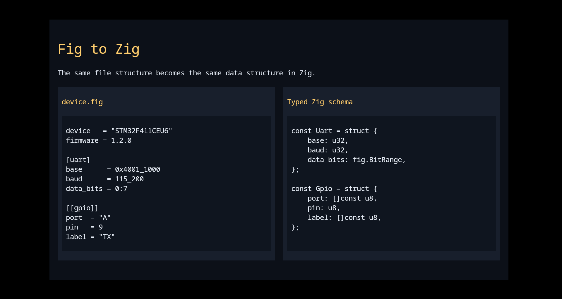
Mapping Model
The consumer-facing surface stays simple on purpose. The caller supplies a normal Zig type, and the
mapper fills it directly using ordinary fields, slices, nested structs, fig.Version,
fig.BitRange, and support types such as fig.Map(T).
Result(T) owns the parsed value and the heap allocations it references.fig.Tag lets a mapped struct receive the header tag that opened it.fig.Map(T) is the clean target type for tagged table sequences.
Built On Munch And Backed By Validation
This repo is where Munch becomes real. The Fig lexer and parser are written as normal Zig modules on
top of Munch, then the repo adds the Fig-specific structural passes and typed mapping that Munch alone
is not supposed to provide.
fig-check validates both syntax and structural rules from the command line.- The build splits lexer, parser, and mapper tests so the language surface can be checked in layers.
- Repeated tagged declarations, dotted integer paths, and merged sequence rules are covered in dedicated tests rather than treated as incidental behavior.
- Zig parser and mapper for the Fig spec.
- Built with Munch, then extended with Fig-specific merge and typing passes.
const fig = @import("fig");

const Config = struct {
    name: []const u8,
    version: fig.Version,
    radio: struct {
        frequency_mhz: u16,
        tx_power_dbm: i8,
    },
};

var result = try fig.parseFile(Config, alloc, "bitwands.fig");
defer result.release(alloc);
Quick start
The easiest way to approach fig-zig is as a typed parser library. Define the Zig shape
you actually want, write a matching .fig file, parse it, then keep the
Result(T) alive for as long as you need the mapped data.
- Add
fig to build.zig.zon and import it into your root module.
- Write a
.fig file with the values you want to edit outside the binary.
- Define a Zig struct with matching field names and types.
- Call
fig.parseFile(...) or fig.parseBytes(...), then read result.value.
- Keep the
Result(T) alive for as long as you need any slices or nested allocations owned by the parsed value.
- Run
fig-check when you want syntax and structural validation without writing a consumer first.
Typed config parse
const std = @import("std");
const fig = @import("fig");

const Config = struct {
    name: []const u8,
    version: fig.Version,
    radio: struct {
        frequency_mhz: u16,
        tx_power_dbm: i8,
    },
};

var result = try fig.parseFile(Config, alloc, "bitwands.fig");
defer result.release(alloc);

std.debug.print("{s}: {d} MHz\n", .{
    result.value.name,
    result.value.radio.frequency_mhz,
});
Tagged sequence mapped into a keyed collection
const Register = struct {
    tag: fig.Tag,
    offset: u32,
};

const Device = struct {
    register: fig.Map(Register),
};

var result = try fig.parseBytes(Device, alloc,
    "[[register: CR1]]\n" ++
    "offset = 0x00\n");
defer result.release(alloc);
Validator usage
cd fig/fig-zig
zig build run -- path/to/config.fig

# or
zig build run-check -- path/to/config.fig
Munch is the lexer and parser toolkit that makes Fig practical. Rules live at comptime, tokenization is
zero-copy, and the parser surface stays close to plain Zig structs and unions.
The important architectural choice is that the grammar model is still just Zig. The lexer is configured
at comptime, the parser is defined in terms of normal structs and unions, and wrapper types add the token
semantics without dragging the whole parser into a separate DSL.
Lexer Architecture
The lexer uses tagged rules and matcher combinators. Every rule is tried at each input position, the
longest match wins, and ties fall back to declaration order. That makes rule ordering matter only for
ties instead of for general correctness.
ByteSet provides comptime character classes with merge and invert operations.Matcher.literal, span, set, prefix, and delimiter cover most token patterns.- Unmatched bytes become
ERR tokens instead of killing the token stream.
Parser Architecture
On the parser side, the main pieces are Token, Skip, Many,
Optional, and Drain. Those wrappers let the parser keep the AST shape close
to the grammar shape while still supporting recovery and recursive types.
Drain(T) is especially important for whole-document parsing with diagnostics.- Token bytes are zero-copy slices into the original source buffer.
- Recursive ASTs can use pointers and are freed automatically by
result.release(...).
- Comptime lexer rules with maximal munch behavior.
- Recursive-descent parsing with recovery via
Drain.
const ByteSet = munch.lex.ByteSet;
const Matcher = munch.lex.Matcher;

const alpha = ByteSet.from("abcdefghijklmnopqrstuvwxyzABCDEFGHIJKLMNOPQRSTUVWXYZ");
const digit = ByteSet.from("0123456789");
const alnum = alpha.merge(digit);

const MyLexer = munch.lex.Lexer(.{
    .rules = &.{
        .{ .tag = .identifier, .matcher = Matcher.span(alpha, alnum) },
        .{ .tag = .number, .matcher = Matcher.set(digit) },
        .{ .tag = .equals, .matcher = Matcher.literal("=") },
        .{ .tag = .whitespace, .matcher = Matcher.set(ByteSet.from(" \t")) },
        .{ .tag = .newline, .matcher = Matcher.literal("\n") },
    },
});
Quick start
The easiest way to learn Munch is to parse a tiny line-based language. Start with one token set, one
AST node, and one root parser. Once that works, add more tokens and more node types without changing
the basic shape. The README's end-to-end flow is the right way to approach it: lexer first, AST
second, parser third, diagnostics last.
- Define the lexer rules with
munch.lex.Lexer and the matchers you need.
- Model the grammar with plain Zig structs and wrapper types such as
Token,
Skip, and Drain.
- Configure a parser with
munch.parse.Parser and tell it which token tags to skip.
- Parse a byte buffer, then inspect the typed result and any diagnostics.
- If you need whole-document recovery, make the root type
Drain(T) instead of a single statement node.
- Add recursive pointers only after the flat version is already working.
Simple parse target
const Token = munch.parse.Token;
const Skip = munch.parse.Skip;
const Drain = munch.parse.Drain;

const Assignment = struct {
    name: Token(.identifier),
    _eq: Skip(.equals),
    value: Token(.number),
};

const Parser = munch.parse.Parser(.{
    .lexer = MyLexer,
    .root = Drain(Assignment),
    .skip = &.{ .whitespace, .newline },
});

var result = try Parser.parse(alloc, "score = 42\n");
defer result.release(alloc);
Diagnostics and recovery
if (result.hasErrors()) {
    for (result.diag) |d| {
        std.debug.print("{}:{}: expected {s}, found {s}\n",
            .{ d.loc.line, d.loc.col, d.expected, d.found });
    }
}
Jig generates thin, typed register-access layers from structured hardware manifests. It exists to keep
the generated APIs readable and reject bad hardware descriptions early.
The project/target/block split is the center of the tool. The manifest hierarchy becomes the generated
namespace hierarchy, so the keys and paths you write directly shape the output tree and import surface.
Manifest Architecture
Jig reads a three-layer Fig tree: project.fig -> target.fig(s) -> block.fig(s). A project
names the generated HAL, each target names a chip family or variant, and each block describes the
registers, groups, and buffers for one peripheral region.
target.<key> controls both the target directory and the hal.<key> namespace.block.<key> controls filenames and target-level re-export names.block.name must match the block key because it becomes the top-level generated declaration.
Generation Pipeline
The generator parses the project first, then each target, then each block. During that process it
validates field widths, access policy, overlaps, and array configuration so invalid definitions fail
at generation time instead of leaving questionable Zig in the output tree.
- Targets emit
info.zig and a target re-export file.
- Blocks emit the typed register API plus any helpers they need.
hal.zig is the intended consumer entry point.
Why Fig Fits Jig So Well
Fig’s tagged tables and declarative path rules are not incidental here. They are the reason Jig manifests
can stay readable while still describing nested hardware structure. A tag like reset or
gpio becomes a structural name you can reopen later, which keeps the manifest close to how
people already talk about registers and peripheral groups.
target.rp2040.path becomes both a filesystem location and the generated hal.rp2040 namespace.[[register: reset]] creates one named register entry that later headers can reopen.[[reset.field: uart0]] walks back through that tag and appends field metadata to the same register.[[gpio.register.ctrl.field: funcsel]] extends the same idea one level deeper for arrayed register groups.
- Reads a three-layer manifest tree: project, target, and block.
- Emits register APIs that stay close to the input model.
name = "demo_hal"
build_path = "src/jig"

[target.rp2040]
path = "hardware/rp2040.fig"
Quick start
Jig is easiest to understand as a manifest-to-code pipeline. You describe the chip tree in Fig, run
the generator once, and then treat the generated files as a normal Zig module. The first pass does not
need a full chip definition. One target and one block is enough to see the shape. It helps to read the
generated Zig immediately so the mapping between manifest and API is obvious.
- Write a
project.fig that names the generated HAL and points at one or more targets.
- Write a target manifest that points at one or more block manifests.
- Describe registers, groups, and fields in the block manifest.
- Run
zig build run -- path/to/project.fig, then import the generated
hal.zig from application code.
- Read the emitted target and block files before layering more blocks on top.
- Rely on the generator’s validation instead of treating invalid manifests as input you can fix later in firmware.
1. Root project manifest
name = "demo_hal"
build_path = "src/jig"

target.rp2040.path = "hardware/rp2040.fig"
2. Target manifest
name         = "rp2040"
manufacturer = "Raspberry Pi Ltd"
revision     = "B2"

block.resets.path   = "resets.fig"
block.io_bank0.path = "io_bank0.fig"
3. Block manifest with tagged register fields
name        = "resets"
address     = 0x4000_C000
width       = 32
description = "Peripheral Reset Controller."

[[register: reset]]
offset      = 0x00
description = "Peripheral reset control."

[[reset.field: uart0]]
bits   = 22:22
access = .RW
reset  = 1

[[reset.field: usbctrl]]
bits   = 24:24
access = .RW
reset  = 1
Generated consumer code
const hal = @import("jig/hal.zig");

const before = hal.rp2040.resets.reset.read();
_ = before.uart0;

hal.rp2040.resets.reset.write(.{
    .uart0 = 0,
    .usbctrl = 0,
});
Arrayed register-group example
name        = "io_bank0"
address     = 0x4001_4000
width       = 32
description = "IO bank 0."

[[register_group: gpio]]
offset      = 0x00
count       = 30
stride      = 8
description = "GPIO status and control."

[[gpio.register: ctrl]]
offset      = 0x04
description = "GPIO control."

[[gpio.register.ctrl.field: funcsel]]
bits   = 0:4
access = .RW
reset  = 31
Generated arrayed use
const ctrl0 = hal.rp2040.io_bank0.gpio(0).ctrl().read();
_ = ctrl0.funcsel;

hal.rp2040.io_bank0.gpio(0).ctrl().write(.{
    .funcsel = 5,
});
Jig-RP2040 owns the bare-metal RP2040 firmware path: boot2, startup, interrupt registration, packaging,
and UF2 output. It keeps startup minimal and pushes board policy into the application or modules.
This stage makes the RP2040 image format explicit. The build does more than compile a binary. It
produces boot2, combines it with the app image, appends the CRC where needed, and emits a ready-to-flash
UF2 while still exposing the generated RP2040 register blocks to the application.
Pipeline Architecture
The README is very clear about the internal split: boot2.zig brings up XIP,
startup.zig owns reset and vector-table entry, registry.zig defines the
interrupt declaration surface, and the host-side helpers package the exact final bytes.
addFirmware(...) is the main build API for consumers.rp2040 is the generated register import used by app modules.boot2crc, bin2uf2, and concat handle packaging details.
Boot Model
The runtime path is ROM bootloader to boot2, then app vector table at 0x10000100, then
startup entry into app.main(). Unregistered interrupt slots default to a silent trap, so
applications can decide which failures deserve visible behavior instead of inheriting a noisy default.
- Boot2 is always built
ReleaseSmall.
- The app image begins at
0x10000100.
zig build jig regenerates the checked-in RP2040 HAL source when hardware definitions change.
- Builds ready-to-flash RP2040 images directly from Zig.
- Exposes comptime interrupt registration and generated RP2040 blocks.
const fw = jig_rp2040.addFirmware(b, dep, .{
    .app_module = app,
});

b.installFile(fw.uf2, "firmware.uf2");
Quick start
This package turns a normal Zig module into a flashable RP2040 image. The shortest path is: define an
app module, hand it to addFirmware(...), then export a main function from
src/main.zig. Once that works, add interrupt handlers and supporting modules. The tool
stays deliberately minimal at startup so board policy still lives in your application code.
- Add
jig-rp2040 as a dependency and create an app module rooted at
src/main.zig.
- Import the generated
rp2040 and optional registry modules in
build.zig.
- Export
pub fn main() noreturn from the app module.
- Run
zig build and flash the generated UF2 from zig-out/.
- Add
handlers only for the IRQ slots you truly own.
- If you change the RP2040 hardware definitions, regenerate the HAL with
zig build jig and commit the output.
Small app module
const registry = @import("registry");

pub const handlers: registry.Registry = .{
    .isr_irq5 = handleUsb,
};

fn handleUsb() callconv(.{ .arm_aapcs = .{} }) void {}

pub fn main() noreturn {
    while (true) {}
}
Build-side integration
const dep = b.dependency("jig_rp2040", .{});

const app = b.createModule(.{
    .root_source_file = b.path("src/main.zig"),
});
app.addImport("rp2040", dep.module("rp2040"));
app.addImport("registry", dep.module("registry"));

const fw = jig_rp2040.addFirmware(b, dep, .{
    .app_module = app,
});
The HAL sits between generated RP2040 register access and application code. It uses explicit ownership
boundaries instead of a hidden board object, which keeps clocks, GPIO muxing, and lifecycle decisions visible.
The README frames this as the main design principle: singleton controller modules own hardware blocks,
instance drivers own one external device, and the caller still owns board-level sequencing and mux setup.
That makes the package easier to reason about than a single global board abstraction.
Architecture
The repo sits on top of jig-rp2040 and below application code. It provides top-level
modules such as gpio, time, i2c, spi,
uart, usb, clocks, and power, then instance
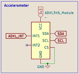
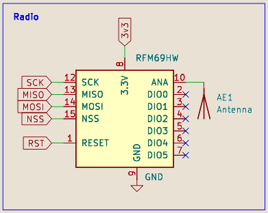
drivers like adxl345.Device and rfm69.Device compose those controllers.
time owns TIMER alarm 0 and TIMER_IRQ_0.usb.CdcSerial owns PLL_USB, clk_usb, and USB controller lifetime.power.dormant assumes the caller already moved the system into a dormant-safe clock state.
Bring-Up Pattern
The recommended order is explicit too: let jig-rp2040 handle startup, set clocks if you
need to, initialize the singleton controllers you need, then create instance drivers on top. The
caller still owns GPIO muxing, pad setup, and cross-module sequencing.
- Use
init() / deinit() to return blocks to known baselines.
- Keep singleton state and device-instance state mentally separate.
- Use the repo’s tests and generated-API compatibility checks when changing low-level behavior.
- Singleton modules own hardware blocks such as GPIO, SPI, I2C, time, and USB.
- Instance drivers build on top for specific parts such as the ADXL345 and RFM69.
hal.gpio.init();
defer hal.gpio.deinit();

hal.time.init(.{ .watchdog_tick_cycles = 12 });
defer hal.time.deinit();

hal.gpio.toggle(25);
hal.time.sleep(125_000);
Quick start
The main HAL pattern is explicit ownership. You initialize the singleton controller modules you need,
then build device drivers on top of them. Nothing silently claims clocks, GPIO muxing, or interrupt
slots for you, which keeps board policy visible in the application. The README’s bring-up order is the
right mental model to follow whenever the package feels verbose.
- Add
rp2040-hal to your firmware build and import it as
const hal = @import("rp2040_hal");.
- Initialize the singleton modules you need, such as GPIO, time, SPI, I2C, or USB.
- Create device instances like
adxl345.Device or rfm69.Device only after
their bus controller is ready.
- Deinitialize modules when you want to return hardware to a known baseline.
- Keep board-specific pin muxing outside the package, because the repo intentionally leaves that policy with the caller.
- Reach for
zig build test when you change timing math, driver behavior, or ownership rules.
Simple sensor bring-up
hal.gpio.init();
defer hal.gpio.deinit();

_ = try hal.i2c.init(.{
    .controller = .i2c0,
    .clk_sys_hz = 125_000_000,
    .baud_hz = 400_000,
});
defer hal.i2c.deinit(.i2c0);

var accel = try hal.adxl345.Device.init(.{
    .controller = .i2c0,
    .pins = .{ .chip_select = 17 },
    .address = .alt_low,
});
defer accel.deinit();

const sample = try accel.readSampleMg();
_ = sample;
USB CDC serial shape
const Serial = hal.usb.CdcSerial(.{
    .reference_hz = 12_000_000,
});

try Serial.init();
defer Serial.deinit();

while (true) {
    Serial.poll();
}
Loom is a framework for firmware drivers. In this project it matters mainly through USB device support,
where it provides protocol logic and state machines while the hardware layer supplies thin hooks.
The USB framework is built around a clean split: generic USB protocol logic stays in Loom, and the
board-specific side only has to implement the HAL contract. That works well as the USB layer underneath
the RP2040 HAL and the BitWands hub/gateway path.
Architecture
The README describes three cooperating layers: UsbCore, DriverPolicy, and
the state machines. UsbCore handles control transfers and standard requests, the policy
owns the function-class behavior, and the state machines keep bus and endpoint phases explicit.
UsbCore handles GET_DESCRIPTOR, SET_ADDRESS, SET_CONFIGURATION, and EP0 transfer phases.DriverPolicy provides class descriptors, setup handling, and write semantics.- The current practical focus is CDC ACM virtual serial support.
HAL Contract
The configuration type you give Loom is checked at compile time. It provides device identity,
controller lifecycle, endpoint zero operations, general endpoint I/O, and address management. CDC mode
adds endpoint layout and optional callbacks for control-line and line-coding behavior.
getDeviceId, getDeviceDescriptor, and getDeviceLanguages define identity.nextEvent() feeds the runtime event loop.cdc_config picks endpoint numbers, packet sizes, and the notification interval.
- Separates generic USB behavior from the board-specific HAL contract.
- Supports CDC ACM for the host-visible hub and gateway path.
const usb = @import("loom").usb;

const Device = usb.CdcDriver(HalConfig, .{});

var device = Device{};
device.init();
while (true) device.poll();
Quick start
Loom pays off when you want protocol logic without rewriting the whole driver stack for each MCU. For a
first pass, define one USB configuration type, expose the required lifecycle hooks, and let the
framework own the USB state machine. Once that is working, the next useful additions are identity
strings, CDC callbacks, and better endpoint-complete handling.
- Define a
HalConfig type that satisfies the USB HAL contract.
- Provide the CDC endpoint configuration and the device identity callbacks.
- Create a driver such as
usb.CdcDriver(HalConfig, .{}).
- Call
init(), then keep polling in the main loop and use the driver methods for I/O.
- Add callbacks like
onRx and onControlLineStateChanged only after the transport basics work.
- If you need another USB function class later, extend the driver policy layer rather than copying the CDC path.
Small CDC configuration slice
const usb = @import("loom").usb;

const HalConfig = struct {
    pub const cdc_config = usb.Types.CdcConfig{
        .ep_notification = 2,
        .ep_data_out = 3,
        .ep_data_in = 3,
        .max_packet_notification = 8,
        .max_packet_bulk = 64,
        .notification_interval = 16,
    };

    pub fn onRx(data: []const u8) void {
        _ = data;
    }
};
Identity and poll loop
pub fn getDeviceLanguages() usb.Types.DeviceLanguages {
    return .{
        .language_id = 0x0409,
        .strings = &.{
            .{ .kind = .manufacturer, .content = "BitWands" },
            .{ .kind = .product, .content = "Hub Receiver" },
            .{ .kind = .serial, .content = "001" },
        },
    };
}

var device = Device{};
device.init();
while (true) device.poll();
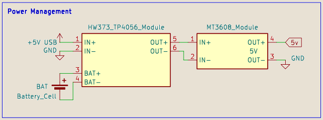
The firmware package is the canonical build root for the application, the OTA bootloader, the USB gateway,
and the Linux-facing host bridge. It is where the project becomes one working system instead of a set of parts.
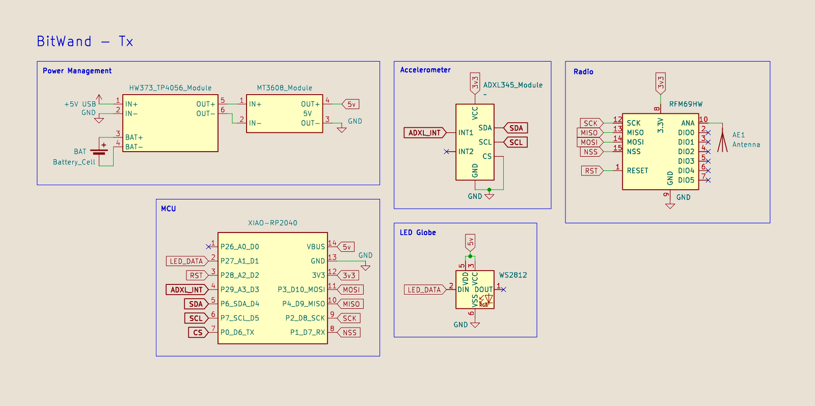
It also carries the glue that ties the reusable libraries together: board definitions, device IDs, RF
protocol behavior, host-visible message shapes, and the targets used during bring-up and demo prep.
Repository Architecture
The README lays out the main split clearly. The RFM69 runtime code handles wand and hub behavior,
orientation code handles the motion sensor path, boot3 and gateway code handle OTA installation, and
the Linux host bridge republishes receiver state to the rest of the project.
src/rfm69/orientation_tx.zig and orientation_rx.zig are the wand and hub cores.orientation_payload.zig and usb_hub_protocol.zig define the narrow machine-readable boundaries.boot3.zig, gateway_ping.zig, and hub_repl.zig form the OTA install path.host/bitwandsd.py bridges the hub to a local AF_UNIX socket.
Behavioral Rules
The wand and hub rules matter just as much as the file layout. On boot the wand reports
unknown to clear stale hub state. During normal operation it waits for acknowledgements
before committing visible state, and after long retry failure it falls back to unknown.
- On dormant wake, the wand re-reports its last known state instead of resetting to
unknown.
- If a wand stays quiet for too long, the hub expires it back to
unknown.
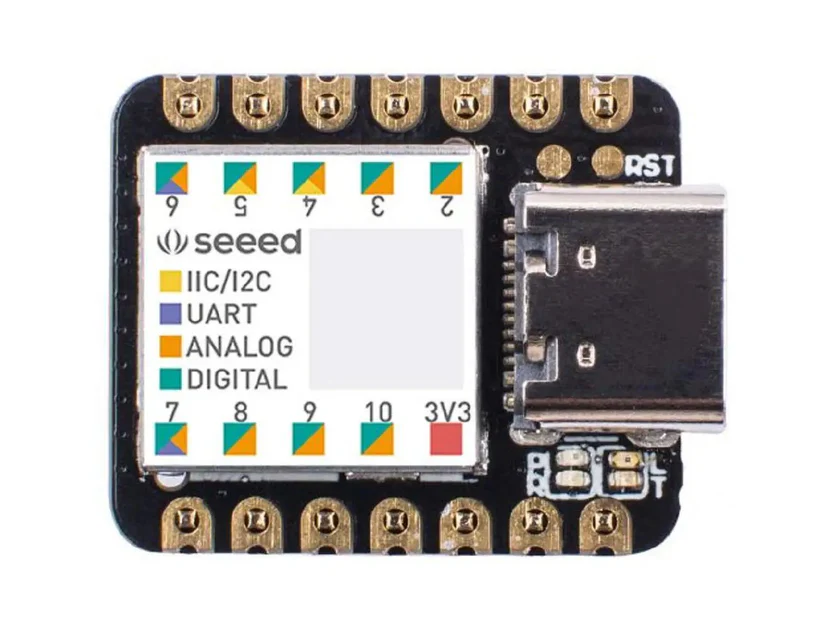
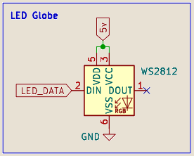
- The XIAO onboard NeoPixel mirrors the external one-wire LED colors.
- Wand transmitters report orientation and wait for matching acknowledgements.
- Hub firmware exports a machine-readable USB CDC protocol to the Linux side.
{"type":"state",
 "dongle_connected":true,
 "known_mask":5,
 "set_mask":1,
 "states":["set","unknown","clear"]}
Host-Visible Protocol
The host boundary is intentionally small. The hub reports readiness, answers simple health checks, and
publishes aggregate state snapshots or updates. That lets the Linux daemon, the presentation, and small
debugging tools all consume the same information without another API layer on top.
READY and PONG make link health easy to test.STATE messages carry the aggregate masks and per-wand view.- The line protocol is simple enough to inspect manually while still being machine-readable.
Project Workflow
The firmware tree expects jig-rp2040, loom, and rp2040-hal as sibling
repos. There are three main workflows: build wands and hub, work on OTA components, or run the Linux
bridge so the rest of the project can subscribe to live state.
- Build a specific device target when you are focused on one path, or use
zig build bitwands for the full wand-and-hub set.
- Use
boot3, gateway-ping, hub-repl, and app-demo targets for OTA work.
- Run
python3 host/bitwandsd.py to expose aggregate state to host-side tools and the presentation runtime.
Core commands
cd firmware
zig build bitwands
zig build rfm69-orientation-tx -Ddevice-id=3
zig build gateway-ping
zig build hub-repl
python3 host/bitwandsd.py
fwtool is a small Zig command-line utility for hardware-oriented flashing tasks. Its current scope is narrow
on purpose: detect an RP2040 in BOOTSEL mode, copy a UF2, and wait for it to disconnect cleanly.
That narrow scope is a feature for this project. The job was to remove one repetitive source of friction
during testing, not to build a universal flashing framework.
Architecture
The command surface is intentionally small: fwtool rp2040 flash <path-to-firmware.uf2>.
The utility looks for the BOOTSEL drive, copies the UF2, and waits for disconnect. It does not try to
become a full serial monitor or board database.
- BOOTSEL mount detection is Linux-specific.
- The tool searches the common
/run/media and /media mount locations.
- Current scope is copy-and-disconnect, not runtime board management.
Current Limits
The README is explicit about the current limits, and they are useful limits to call out because they
keep expectations realistic during development.
- Only
rp2040 flash is implemented.
- The UF2 path is required; there is no default firmware path.
- There are no aliases, reset helpers, probe commands, or monitor commands yet.
- Simple hardware-first command layout.
- Designed as a practical frontend rather than a generic device manager.
fwtool rp2040 flash zig-out/bin/firmware.uf2

// Finds the RPI-RP2 volume
// Copies the UF2
// Waits for the volume to disconnect
Quick start
fwtool is deliberately small, so the tutorial is mostly about workflow. Build the tool,
put the board in BOOTSEL mode, then flash a UF2 directly. There is no hidden board database or monitor
layer. It just finds RPI-RP2, copies the file, and waits for the drive to disappear. That
waiting step matters because it keeps the command from returning before the board transitions away from the mass-storage path.
cd fwtool and run zig build to build the utility.- Put the RP2040 board into BOOTSEL mode so it mounts as
RPI-RP2.
- Run
zig build run -- rp2040 flash path/to/firmware.uf2 while working locally.
- Optionally install the binary and use
fwtool rp2040 flash ... directly after that.
- If flashing fails, verify the board is actually in BOOTSEL mode and check the expected mount paths first.
Simple workflow
cd fwtool
zig build
zig build run -- rp2040 flash ../firmware/zig-out/bin/hub_firmware.uf2

# or, after install
fwtool rp2040 flash ../firmware/zig-out/bin/wand_3_firmware.uf2
Mount search paths
/run/media/RPI-RP2
/media/RPI-RP2
/run/media/$USER/RPI-RP2
/media/$USER/RPI-RP2
The capstone deck is also part of the project. It is a standalone Zig presentation runtime that uses kitty,
retained widgets, live command panes, and authored slide content instead of exported slide images.
That turned the presentation into a real system component. It had to consume project artifacts, show live
state, and handle the same runtime constraints and demo pressure as the rest of the stack.
Architecture
The build defines both a reusable module and a standalone executable. The public module re-exports
pieces like widgets, presentation, layout,
render, and theme, while runtime internals such as kitty handling and PTY
sessions stay behind the internal boundary.
src/root.zig defines the public surface.src/main.zig owns the standalone presenter loop.src/bitwands_deck.zig holds the authored BitWands-specific deck content and support loading.build.zig installs the images and the state-view script alongside the executable.
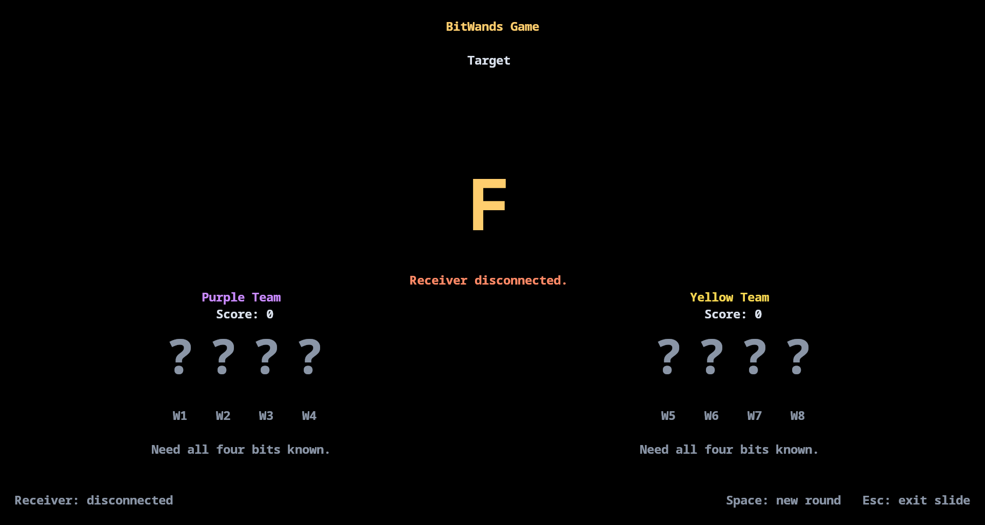
Runtime Flow
At startup the executable checks for kitty and a real TTY, enters raw mode and the alt screen, loads
deck assets, then hands control to the presenter runtime. That runtime choice is why the deck can show
live state panes and command output rather than static screenshots.
kitty.requireKitty(...) rejects unsupported terminals early.presenter_runtime owns redraws, slide navigation, and event handling.scripts/bitwands_state_view.py provides a smaller companion panel for live receiver state.
- Runs as a real terminal application with its own runtime constraints.
- Holds the project narrative, live demos, and supporting images in source.
kitty.requireKitty(stdin, stdout) catch |err| switch (err) {
    error.NotATerminal, error.KittyRequired => return,
    else => return err,
};

try deck.init(allocator, assets, support);
Project Workflow
The usual workflow is to edit the deck or runtime pieces, rebuild, and rerun inside kitty. The deck is
not separate content pasted on top of the runtime. It is source code and assets that live in the same
package as the runtime itself.
cd presentation and run zig build to build the runtime and install local assets.- Run
zig build run inside kitty.
- Edit
src/bitwands_deck.zig for slide content and project-specific live panes.
- Use
python3 scripts/bitwands_state_view.py when you want a smaller live state panel.
Public surface and run loop
pub const widgets = @import("widgets.zig");
pub const presentation = @import("presentation.zig");
pub const layout = @import("layout.zig");
pub const render = @import("render.zig");
pub const theme = @import("theme.zig");
cd presentation
zig build
zig build run
python3 scripts/bitwands_state_view.py
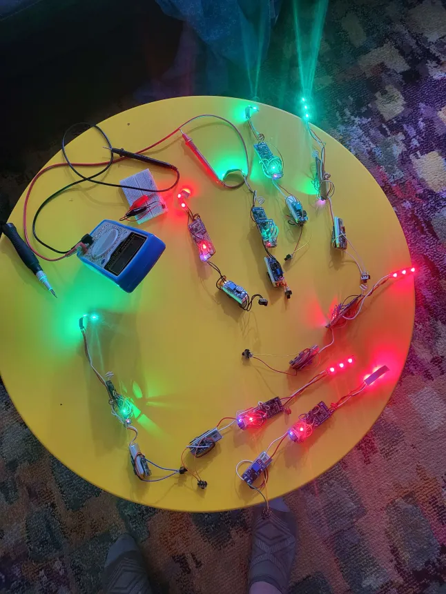
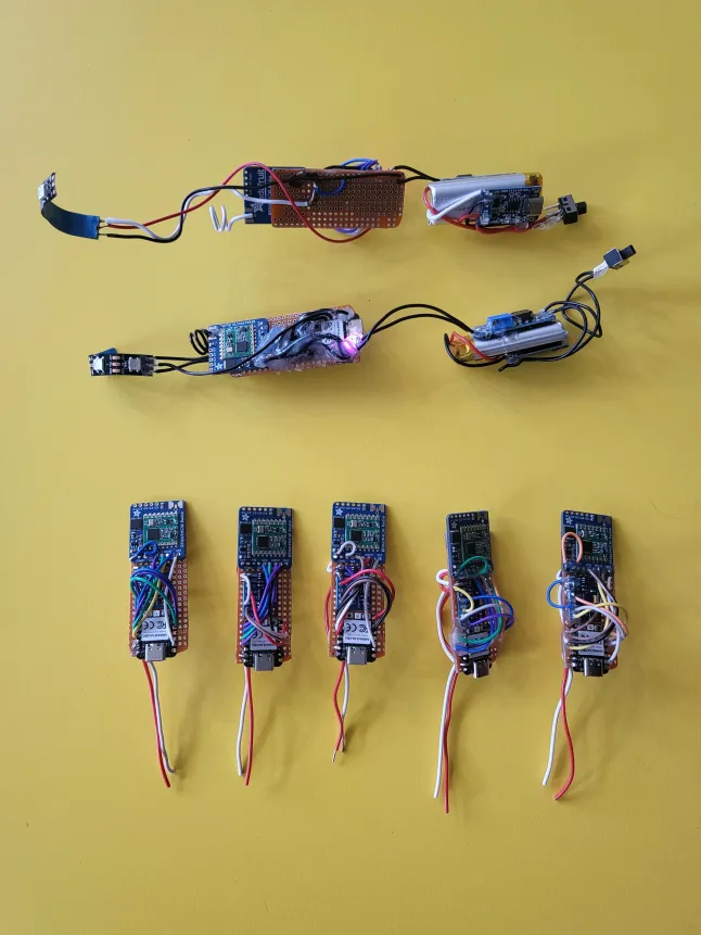
See runtime screenshots below